-
 Shear with safety cutting system apt to process steel in bars. There is no continuous cutting, which means that each cutting motion is individually controlled. Capacity: 1 bar Ø 36mm, 2 bars Ø 28mm and 5 bars Ø 16mm. 15 cuts per minute.
 -
 The main body is one-block in high-quality cast steel, reinforced in the points where the stress is higher, without any welded plate. The cutting blades, made in special hardened steel, are designed to cut both small and big diameter iron. Gears are in wear-resistant steel, continuously lubricated, and the moving parts are in hardened and rectified steel.
GENERAL FEATURES RPM per 1' 60 Power Kw 3 Weight Kg 470 Dimension (LxLxH) 60x100x85 CUTTING CAPACITY Bar No.bars No.bars No.bars No.bars No.bars 1 2 3 4 5 Res.650N/mm² Ø max 34 Ø max 24 Ø max 18 Ø max 14 Ø max 12 Res.850N/mm² Ø max 30 Ø max 20 Ø max 16 Ø max 12 Ø max 10 -
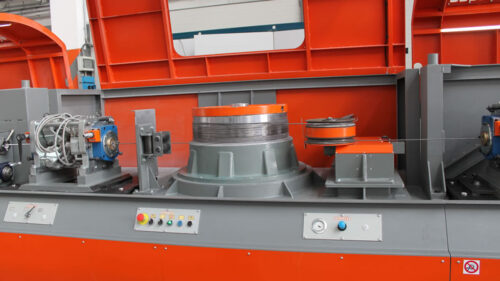
 Shear with flywheel cutting system capable to cut bars. (1 bar Ø 40 mm Speed: 50 Cuts per minute.) Shear with flywheel cutting system capable to cut bars. (1 bar Ø 40 mm and 2 bars Ø 32 mm). There is no continuous cutting, which means that each cutting motion is individually controlled. The equipment is operated through cascade gears driven by an electric motor. Speed: 60 Cuts per minute.
 -
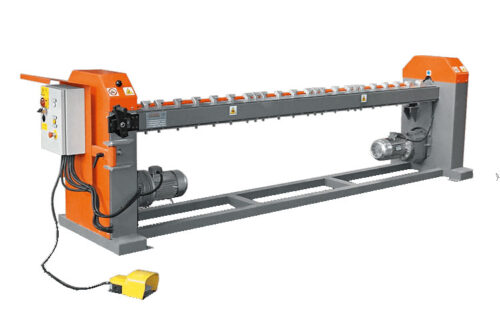
 Ring bending equipment for rings of unlimited radius (rib rings) and spirals. Driven by a variable-speed electric motor: min 20; max 30 rpm. Adjustable bending radius from a minimum 15 cm (with small diameters) and over. For Ø 6-32 mm wires.
 -
 Radius machine for the production of circles, spirals and radius bars for diameters from 6mm to 40mm. The machine uses a system of 4 rollers, one of which is specifically to ensure the stability and consistency of the radius of the curve. The CER40 can be programmed to produce automatically up to 5 different radius curves on the same bar thanks to the measuring system. Speed: min 13m/min, max 42m/min.
 -

 Software module that allows automatically importing the data of the longitudinal beam reinforcements according to the working drawings. The table must explicitly contain the drawing of the rods of these longitudinal reinforcements. CLIC-CAD recognises shapes, lengths and diameters of the reinforcement rods in the drawings and imports the data directly to our GO management software for the subsequent working procedures (cutting optimisation, label printing, sending the production data to the machines, reports, statistics, etc.). CLIC-CAD thus allows: -Drastically reducing the workload of those who convert the drawings into job lists - Reducing operator input errors.
 -
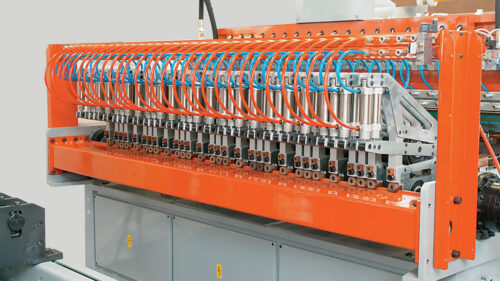
 IDEA assembles cages by means of the patented 'Schnell System' (Patented): using three thin longitudinal wires, which may be welded to any point of the stirrup's exterior surface IDEA is able to half-assemble lattice girders of stirrups of any shape and size. Its operation is extremely simple: stirrups are fed; next they are welded to the three longitudinal wires by the welding clamps; the whole girder is made to slide forward while its motion is previously set by the computer and may be constantly checked. The half-assembled girder is now ready to be finished off by fixing the frame carrying bars. Fixed welding unit. 3 welding heads each unit may be moved to different positions both in height and lengthwise and may rotate to reach the ideal welding point. The vertical positioning is performed by a gearmotor. Fixed welding unit. 3 welding heads each unit may be moved to different positions both in height and lengthwise and may rotate to reach the ideal welding point. The vertical positioning is performed by a gearmotor. Mobile traction unit. It consists of: 1 mobile head which is driven by an electronic motor along the girder supporting framework and is equipped with 3 vices to clamp/release the longitudinal wires. Girder traction frame. The pitch may be set on the computer. Central framework It consists of a supporting framework where the half-assembled lattice girder slides during manufacture and slides to remove assembled girders. Industrial computer mod. 'Idea-Control', designed to work in very harsh environments. It is equipped with an alphanumeric display and manages all the functions performed by the machine.
 -

The cage making machine CM PRO 110, produces cylindrical and prismatic poles with welded spiral and programmable pitch (Ø 1100 mm), but thanks to equipment with a set of servomotors, the new monobloc structure and other major innovations, it is a more flexible, faster, safer, innovative and transportable machine.
The rods located in the holes of these plates form dials which separate the rebars being fed to the machine to fabricate the cage. The dial is anchored to the fixed plate, thus following its rotation. It lies on the storage boxes by means of polyurethane-coated rollers located at one end of metal rods.
Their function is to support the cage during its fabrication. They are raised automatically and stopped as soon as the supporting rollers reach the cage.
Fixed plate
Bored plate rotating in a synchronised way with the mobile plate. Once you have set the diameter of the cage you are going to produce, the bushes are placed and secured to the plate. The rebars fed through the dial are then made to slide through these bushes.Mobile plate
Cages are produced by moving the mobile plate forward and forming a spiral around the rebars. The suspended mobile disk attached to the main structure and equipped with servomotors to give it greater accuracy and speed.Thanks to the suspended mobile disk, an innovative cage evacuation system with hydraulically-operated chutes could be designed and applied: a crane is no longer required to evacuate the cage and the machining cycle can immediately be resumed.
Thanks to the suspended mobile disk, an innovative cage evacuation system with hydraulically-operated chutes could be designed and applied: a crane is no longer required to evacuate the cage and the machining cycle can immediately be resumed.
The new CM 1100 xp control is incorporated in the base structure so that the machine takes up less space, at the same time freeing the operator working area. It is fitted with a touch screen, flash memory, and provision has been made for a serial line. In addition, it allows changing the cage execution speed without interrupting the working cycle, producing cages with variable pitch, defining how many cross-pieces to weld and automatically lifting the supports.
-

 Machine for the production of cylindrical cages with variable pitch welded spiral wrap (Ø 1600 mm). High productivity and flexibility is guaranteed by the configuration of the machine and by the fully automatic welding unit SAF 3000. It is also possible to produce on the machine square or rectangular cages and cages with the bars bent on the end (90° bends, bottle necks and pointed).
 -
 Cage making machine for the production of round cages with welded spirals and pre-set pitch. The machine is characterized by a reduced longitudinal length. The welding process is performed by a mobile unit and the bar loading zone is a telescope, for this reason, during the welding operation, the length decreases while the welding head moves forward. Unwinding pay-off Placed at the side of the machine’s body, it holds the coil that is going to produce the spiral. The pay-off moves together with the mobile disk where the welding machine has been placed. Ray Its aim is that of separating the bars that are going to produce the cage. The ray is hooked to the mobile disk, therefore it has the same rotating movement and it reduces itself while the welding head moves forward. Their function is to support the cage during its fabrication. They are raised automatically and stopped as soon as the supporting rollers reach the cage. Fixed plate Bored plate rotating in a synchronised way with the mobile plate; its clamps are used to secure the rebars. Mobile plate This plate is bored in the same way as the fixed plate. Once you have set the diameter of the cage you are going to produce, the bushes are placed and secured to the plate. The rebars fed through the dial are then made to slide through these bushes. Cages are produced by moving the mobile plate forward and forming a spiral around the rebars. Fixed plate Bored plate rotating in a synchronised way with the mobile plate; its clamps are used to secure the rebars. Mobile plate This plate is bored in the same way as the fixed plate. Once you have set the diameter of the cage you are going to produce, the bushes are placed and secured to the plate. The rebars fed through the dial are then made to slide through these bushes. Cages are produced by moving the mobile plate forward and forming a spiral around the rebars. The new CM PRO Telescope control is incorporated in the base structure so that the machine takes up less space, at the same time freeing the operator working area. It is fitted with a touch screen, flash memory, and provision has been made for a serial line. In addition, it allows changing the cage execution speed without interrupting the working cycle, producing cages with variable pitch, defining how many cross-pieces to weld and automatically lifting the supports.
 -
 COIL FLIPPER is an efficient patented device for coil handling. Thanks to its innovative design, it can lift and rotate coils from the horizontal to the vertical position in one simple movement.
 -
 COIL SPIDER is a safe and small lifting device that, due to its up-to-date features, can hook from the outside rolled and drawn coils (either rewinded or not). COIL SPIDER is equipped with an automatic release and hiding guns (patented).
 -
 The “Coldrive” 2MV is a cold rolling line with multiple vertical drawing capstan for the production of smooth and ribbed wires from Ø 3,4 to Ø 12 mm. This cold drawing line is completely modular and the rolling process is made through drawing capstan and rollers cassettes for rolling/profiling. Driven by electric asynchronous servomotors digitally controlled.
 -

 The Coldrive MV is a cold rolling line with single vertical drawing capstan for the production of smooth and ribbed wires from Ø 4 to Ø 12 mm. This cold drawing line is completely modular and the rolling process is made through drawing capstan and rollers cassettes for rolling/profiling. Driven by electric asynchronous servomotors digitally controlled.
 -

 The Combidrive MO is a cold rolling line with single horizontal drawing capstan for the production of smooth and ribbed wires in bars from Ø 4 to Ø 12 mm. This cold drawing line is completely modular and the rolling process is made through drawing capstan and rollers cassettes for rolling/profiling. Driven by electric asynchronous servomotors digitally controlled.
 -
 This is the smallest machine of the series. It has been developed to work on elements which do not need large quantities of concrete. Its particular handling and small dimensions allow to reach high translation speed.
 -
 Being already the desire of most of our clients, the MINIBETON of 2 m3 capacity harvest the fruits of many years of experience of our technical research centre.
 -
 SPEEDY: A synonymous of speed, this is the name we gave to this machine over 20 years ago. The immediate success it won, due to its well-known qualities of versatility and economicity, spurred our company to improve the research and the development of solutions guaranteeing a maximum reliability.
 -
 In case of other specific requirements Bianchi Casseforme is able to supply distributing machines like the Dumper model.
 -
 The hook mod. EASY is a device allowing the handling of any loads in a fully safe condition. The releasing device allows the operator to discharge the loads automatically, in a very fast and safe way.
 -

 Mesh welding machine for the production of either reinforcing mesh or fence mesh working with pre-cut wires. Range from Ø 3 to Ø 12 mm. This mesh welding plant is ideal for small mesh producers or as an ancillary machine for big mesh producers. Driven by digital electric servomotors. - High quality mesh panels - Possible upgrade with automatic feeding group for cross wire and line wire - Web Teleassistance
 -

 Mesh welding machine for the production of reinforcing mesh working with pre-cut wires. Range from Ø 3 to Ø 12 mm. Driven by digital electric servomotors.
 -

 Mesh welding machine for the production of reinforcing mesh working with line & cross wires from coils. Range from Ø 3 to Ø 10 mm.
 -
 Mesh welding machine for the production of reinforcing mesh working with line wires from coils and cross wires from pre-cut wires. Range from Ø 3 to Ø 10 mm.
 -

 Mesh welding machine for the production of reinforcing mesh, engineered, special, heavy and 3D (bent, precast) mesh working with pre-cut wires or bars up to Ø 25 mm. This mesh welding line is ideal for the production of both light (Ø5 x Ø5 mm) and heavy meshes (Ø20 x Ø20 mm). Driven by digital electric servomotors.
 -

 Versatile Plant for the production of both standard and engineered mesh welding panels. Max. welding speed up to 80 strokes/min.
 -

 Versatile Plant for the production of both standard and engineered mesh welding panels. Max. welding speed up to 120 strokes/min.
 -

 Machine for automated assembling of mesh cages of AAC panels by welding of vertical connectors. AAC panels are used in the production of floors and roofs, external walls and interior partitions. Driven by digital electric servomotors.
 -
 Automatic cross-wire feeding unit for mesh line from coil. Fly-over straightens cold-drawn or hot-rolled cross wires of a diameter ranging from 3 to 8 mm, falling from a mesh line feeding unit. Maximum pulling speed 160 m/min.
 -

 Electromechanical equipment for cutting of reinforcement mesh. It cuts in two directions thanks to the two kW 3 cutting motors, a kW 0.75 press motor and a kW 0.55 feeding motor.
 -

 Automatic mesh bending machine, equipped with double gearmotor, fast fitting pins and switch for 3 mechanical programs.
 -

 Automatic mesh bending machine, equipped with double gearmotor, fast fitting pins.
 -

 Automatic mesh bending machine, equipped with double gearmotor, fast fitting pins.
 -

 Production supervision software that shows the job execution status in real-time and allows managing the operators and obtaining the real production statistics also for manual machines and by operator. Ethernet is required to connect each data collection point with the office and the bar code readers on the machines.
 -

 Software module that allows issuing quotations, notes and invoices for the rod orders managed with the Graphico software. It allows including data related to the job executed in the notes and invoices thanks to the possibility of interfacing with the Grafo-Trax package. The Graphico software is required.
 -

 Grafo Mesh simplifies the production of meshes, floors, walls and other items having longitudinal and transversal wires. The software interface allows a fast and easy data introduction of the mesh to be produced, indicating the diameter, separation and possible windows. With Grafo Mesh you can produce any kind of mesh, also very complex ones.